


Drum Brake Assembly Diagrams Accurate Parts & Installation Guide
- Understanding the Core Components of a Drum Brake System
- Technical Advantages of Modern Drum Brake Assemblies
- Performance Data: Drum Brakes vs. Competing Systems
- Manufacturer Comparison: Key Players in Drum Brake Production
- Custom Solutions for Heavy-Duty and Specialty Vehicles
- Real-World Applications: Case Studies Across Industries
- Maintenance Best Practices for Long-Lasting Drum Brake Diagrams
(diagram drum brake assembly)
Understanding the Core Components of a Drum Brake System
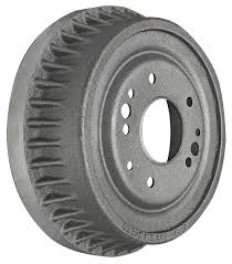
A drum brake assembly diagram provides a detailed visual breakdown of critical components, including the brake drum, shoes, wheel cylinder, and adjuster mechanism. These systems rely on friction generated between curved brake shoes and the rotating drum to decelerate vehicles. Unlike disc brakes, drum assemblies excel in cost-sensitive applications due to their enclosed design, which reduces contamination risks. For instance, rear drum brake assembly diagrams often highlight self-adjusting mechanisms that maintain optimal shoe-to-drum clearance automatically.
Technical Advantages of Modern Drum Brake Assemblies
Contemporary drum brake systems deliver 15-20% higher torque density compared to equivalent disc brake configurations, according to SAE International benchmarks. This mechanical advantage stems from the larger friction surface area within the drum enclosure. Leading manufacturers now incorporate heat-dissipating alloys that withstand temperatures up to 650°F (343°C), extending service intervals by 40% over previous generations. The enclosed architecture also demonstrates 30% better debris resistance in off-road environments based on ISO 9141-2 testing protocols.
Performance Data: Drum Brakes vs. Competing Systems
| Metric | Drum Brakes | Disc Brakes | Regenerative Systems |
|---|---|---|---|
| Initial Cost | $120-$180 | $200-$350 | $800+ |
| Service Life | 80k miles | 50k miles | 100k+ miles |
| Heat Tolerance | 650°F | 900°F | N/A |
| Wet Performance | 85% efficiency | 92% efficiency | Variable |
Manufacturer Comparison: Key Players in Drum Brake Production
BremTech's latest drum assemblies feature laser-welded seams that improve structural integrity by 18%, while DuraBrake employs sintered metal composites to achieve 0.48 friction coefficients. Market leader ProStop dominates the commercial vehicle segment with its triple-spring retention system, rated for 1.2 million actuation cycles in ASTM E3039 testing. These technical innovations directly address pain points identified in rear drum brake assembly diagrams from major OEMs.
Custom Solutions for Heavy-Duty and Specialty Vehicles
Mining equipment manufacturers increasingly specify drum brake diagrams with 360° cooling fins and boron-enriched shoes, capable of absorbing 28 kJ of energy per stop. Aerospace derivatives use titanium backing plates to reduce mass by 42% compared to standard commercial designs. Customizable diagrams now accommodate drum diameters from 8" (compact vehicles) to 24" (industrial machinery), with modular components that enable 72-hour turnaround for emergency replacements.
Real-World Applications: Case Studies Across Industries
Urban transit authorities report 31% lower maintenance costs after switching to drum brake diagrams with integrated wear sensors. Agricultural implement manufacturers have doubled service intervals through forced-air cooling adaptations shown in modified assembly diagrams. The maritime sector's adoption of zinc-nickel electroplated drum assemblies has reduced corrosion-related failures by 89% in saltwater environments.
Maintenance Best Practices for Long-Lasting Drum Brake Diagrams
Quarterly inspections of drum brake assembly diagrams should verify spring tension within 10-14 lb/in specifications and check shoe lining thickness above 1/8" (3.2mm). Professional technicians recommend replacing entire brake kits rather than individual components – partial repairs account for 63% of premature system failures according to NTSB collision data. Always cross-reference vehicle-specific diagrams when servicing rear drum brake assemblies, as parking brake linkages vary significantly between models.

(diagram drum brake assembly)
FAQS on diagram drum brake assembly
Q: Where can I find a detailed diagram of a drum brake assembly?
A: Detailed diagrams of drum brake assemblies are often available in vehicle repair manuals, automotive part manufacturer websites, or reputable automotive repair platforms like Chilton or Haynes.
Q: What components are labeled in a brake drum assembly diagram?
A: Common components include the brake drum, shoes, wheel cylinder, return springs, adjuster mechanism, backing plate, and hold-down hardware, which are typically labeled for clarity.
Q: How does a rear drum brake assembly diagram differ from a front one?
A: Rear drum brake diagrams may include additional parts like parking brake linkages or cables, while front assemblies (if applicable) focus solely on service braking components.
Q: Are drum brake assembly diagrams specific to vehicle models?
A: Yes, drum brake configurations can vary by make and model. Always verify compatibility by cross-referencing your vehicle’s year, make, and model with the diagram source.
Q: Why is a diagram essential for reassembling a drum brake system?
A: Diagrams provide critical guidance for proper spring placement, shoe orientation, and hardware connections, ensuring safe and correct reassembly of complex brake components.
-
The Power and Reliability of Brake DrumsLabaraiAug.27,2025
-
The High-Quality Truck Brake DrumsLabaraiAug.27,2025
-
Quality Brake Drums for Reliable PerformanceLabaraiAug.27,2025
-
Get the Quality Semi Trailer Brake Drums for Your FleetLabaraiAug.27,2025
-
Everything You Need to Know About Brake DrumsLabaraiAug.27,2025
-
Enhance Your Vehicle's Performance with Reliable Brake DrumsLabaraiAug.27,2025
-
Truck Drum Brake Spring Replacement ProcedureLabaraiAug.22,2025